📖 Table of Contents
- 📌 Introduction: What is a Chip Resistor?
- 🧱 What is a Chip Resistor?
- 🔍 Chip Resistor Types and Materials
- 📏 Chip Resistor Sizes and Coding
- 📊 Technical Specifications
- 🧪 How to Use Chip Resistors in Circuits
- 🔧 How to Test or Replace a Chip Resistor
- 🛍️ Where to Buy Chip Resistors (B2B & Distributors)
- 🔄 Chip Resistor Alternatives and Compatibility
- 📚 FAQs about Chip Resistors
- 🧩 Conclusion: Why Chip Resistors Matter in Electronics
📌 Introduction
What is a Chip Resistor?
A chip resistor—also known as a surface mount resistor or SMD resistor—is a compact, rectangular passive component used to limit current flow, divide voltage, or terminate electrical signals in electronic circuits. Unlike traditional through-hole resistors, chip resistors are mounted directly onto the surface of a printed circuit board (PCB), making them ideal for high-density and automated PCB designs.
These resistors are manufactured using either thin-film or thick-film deposition techniques. Their resistance values are marked with industry-standard codes like EIA-96 or 3-digit/4-digit markings. Their size, reliability, and ease of automation have made them an essential component in virtually all modern electronic products.

▲ Various sizes of chip resistors on a PCB (Image: Wikipedia)
▲ Video: How chip resistors work and how to read SMD resistor codes
Why Are Chip Resistors Widely Used in Modern Electronics?
Chip resistors are indispensable in today’s electronic world due to their:
- Compact size: Perfect for miniaturized circuits such as smartphones, wearables, and IoT devices.
- Automated assembly: Compatible with SMT (Surface Mount Technology) for high-speed manufacturing.
- Wide resistance range: From less than 1 ohm to several megaohms, meeting diverse design needs.
- Stable performance: Excellent thermal characteristics and long-term reliability.
As devices continue to shrink in size while increasing in complexity, chip resistors offer the perfect balance of electrical performance and spatial efficiency. They are used in almost every electronic circuit—ranging from mobile phones and automotive control units to LED lighting systems and medical electronics.

▲ Chip resistor used in a mobile device circuit (Image: Electronics-Notes)
🧱 Chip Resistor: Structure, Classification, and Technology
Chip Resistor Internal Structure
A chip resistor is a compact passive component, constructed with layered materials that ensure precision and reliability in circuit performance. Its basic internal structure includes:
- Ceramic Substrate – Provides mechanical strength and electrical insulation
- Resistive Film Layer – Made of metal oxides or conductive inks, this determines the resistance value
- Protective Coating – Prevents moisture and oxidation damage
- End Electrodes – Ensure solderability and electrical contact with PCB pads

▲ Schematic diagram of a surface-mount chip resistor structure
Types of Chip Resistors
Chip resistors come in various types depending on their manufacturing method, material, precision, and use case. The two most common classifications are:
1. Thick Film vs Thin Film Resistors
| Type | Description | Use Case |
|---|---|---|
| Thick Film | Printed resistive ink on ceramic; low cost, general tolerance | Consumer electronics, general circuits |
| Thin Film | Sputtered metal film; high precision, better temperature coefficient | Medical, military, measurement instruments |
2. Other Variants
- Precision Resistors: Tolerance as low as ±0.01%
- High Power Resistors: Designed for power regulation and dissipation
- Anti-surge & Pulse Resistors: Withstand voltage spikes or transient surges
- Automotive Grade: Meet AEC-Q200 standards for vehicle applications
Manufacturing Process of Chip Resistors
Chip resistors are mass-produced using highly automated techniques for consistency and scalability. Here's a simplified overview of the process:
- Start with ceramic substrate preparation
- Apply resistive material (either printed or sputtered)
- Trim the resistor to value using laser or cutting methods
- Apply protective coating and end terminations
- Test resistance, tolerance, and temperature coefficient
▲ Video: How chip resistors are manufactured in surface-mount technology
Why Miniaturization Matters
One key advantage of chip resistors over traditional through-hole types is miniaturization. This not only saves PCB space but also:
- Enables high-density circuit integration
- Improves assembly speed via pick-and-place automation
- Reduces overall cost in high-volume manufacturing
In modern electronics like smartphones, IoT devices, and wearables, component size is critical. Chip resistors—especially in 0201 and 01005 packages—enable compact yet powerful designs.
▲ Comparison of various chip resistor sizes (0603, 0402, 0201, 01005)
🔍 Chip Resistor Types and Materials
Thick Film vs Thin Film Chip Resistors
One of the most important distinctions in chip resistor technology is between thick film and thin film types. These differ in manufacturing methods, cost, accuracy, and applications.
| Type | Manufacturing | Tolerance | Applications |
|---|---|---|---|
| Thick Film | Screen-printing resistive paste on ceramic substrate | ±1% to ±5% | Consumer electronics, general-purpose devices |
| Thin Film | Sputtering metal film on ceramic with laser trimming | ±0.1% to ±0.01% | Medical, aerospace, precision instrumentation |

▲ Visual comparison between thick film and thin film resistors
Precision Chip Resistors
Precision chip resistors are designed for circuits that require extremely tight tolerance and stable performance over temperature and time. These resistors typically use thin film technology and offer:
- Very low TCR (Temperature Coefficient of Resistance), e.g. ±5 ppm/°C
- Tolerances as tight as ±0.01%
- Excellent long-term stability
They're essential in applications such as medical sensors, aerospace systems, and scientific measurement devices.
▲ Video: Precision chip resistors in sensitive electronics
Power Chip Resistors
Power chip resistors are built to handle high current or dissipate large amounts of heat. They are designed with:
- Larger surface area and thicker substrates
- Advanced thermal management for power dissipation
- Ratings from 1W to 10W and more
These are commonly used in LED drivers, power supplies, motor drivers, and EV power electronics.

▲ Example of a high-power surface-mount chip resistor
Common Resistor Materials
The performance and reliability of chip resistors largely depend on the material used for the resistive element. Common materials include:
- Metal Film: Used in thin film resistors; offers high stability and accuracy
- Carbon Film: Lower cost but less stable; used in general-purpose resistors
- Metal Oxide: Offers high temperature resistance and good overload capacity
Advanced applications may also use nichrome (NiCr) or tantalum nitride for specialized resistance characteristics.

▲ Comparison of carbon film and metal film resistors
📏 Chip Resistor Sizes and Coding
Common SMD Package Sizes
Chip resistors are available in standardized SMD (Surface Mount Device) sizes. The most widely used are:
- 0201 – Ultra compact, for space-critical applications
- 0402 – Popular in smartphones and compact IoT devices
- 0603 – General-purpose for consumer electronics
- 0805 – Suitable for moderate power and thermal conditions
- 1206 – Larger size for better heat dissipation and higher power rating

▲ Comparison chart of SMD resistor package sizes
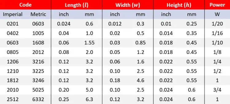
Chip Resistor Size vs Power Rating Table
Each chip resistor size corresponds to a typical power rating. This is crucial in selecting resistors for thermal and electrical stability.
| Package Size | Metric Code | Typical Power Rating | Common Usage |
|---|---|---|---|
| 0201 | 0603 | 1/20 W | Wearables, hearing aids |
| 0402 | 1005 | 1/16 W | Mobile phones, compact modules |
| 0603 | 1608 | 1/10 W | General electronics, routers |
| 0805 | 2012 | 1/8 W | Power supplies, sensors |
| 1206 | 3216 | 1/4 W | Automotive, industrial boards |
How to Read Chip Resistor Codes
Chip resistors use compact coding systems to indicate resistance value. Two major systems are:
- 3-Digit Code: Common in 5% and 1% tolerance resistors. For example,
103means 10 × 10³ = 10kΩ. - EIA-96 Code: Used in 1% precision resistors. It uses a two-digit code and a multiplier letter (e.g.,
24C).

▲ Resistor value codes: 3-digit and EIA-96 system
Example: How to Identify SMD Resistor Values
Let's decode a few real-world examples:
- Code: 472 → 47 × 10² = 4.7kΩ
- Code: 681 → 68 × 10¹ = 680Ω
- Code: 24C (EIA-96) → Lookup "24" = 178, C = ×100 → 17.8kΩ
EIA-96 decoding requires a table reference. Many datasheets provide a complete list or use EIA decoding tools.
▲ Video: How to decode chip resistor markings
📊 Technical Specifications of Chip Resistors
Resistance Range
Chip resistors are available across a wide range of resistance values, typically from 1Ω to 10MΩ, with some special versions offering even higher or lower resistance levels.
- Low resistance (1Ω–100Ω): Common in current sensing and power supply circuits
- Mid resistance (100Ω–100kΩ): Widely used in signal processing, filters, and biasing
- High resistance (100kΩ–10MΩ): Suitable for voltage divider and low-current detection

▲ Typical resistance range in SMD resistors
Precision & Tolerance
Chip resistors come in different tolerance classes, defining how closely the actual resistance matches the nominal value:
- ±5% – General-purpose electronics, cost-effective
- ±1% – Common in signal circuits and consumer electronics
- ±0.1% – High precision, used in measurement and calibration applications
Tighter tolerances help ensure accurate signal conditioning and voltage references in sensitive systems.

▲ Illustration of resistor tolerance levels
Power Rating & Voltage Limits
Each chip resistor is rated for a specific power dissipation (in Watts) and maximum working voltage. Selecting the correct values is crucial to avoid overheating or failure.
| Package Size | Typical Power Rating | Max Working Voltage |
|---|---|---|
| 0402 | 0.063 W | 50 V |
| 0603 | 0.10 W | 75 V |
| 0805 | 0.125 W | 150 V |
| 1206 | 0.25 W | 200 V |
Tip: Always choose a resistor with at least 2x the expected working power for safe operation.
Thermal Stability and Temperature Coefficient (TCR)
The temperature coefficient of resistance (TCR) defines how a resistor’s value changes with temperature. It's measured in ppm/°C (parts per million per degree Celsius):
- ±100 ppm/°C – Standard resistors
- ±25 ppm/°C – Precision resistors
- ±5 ppm/°C – Ultra-precision foil resistors
Lower TCR values ensure better thermal stability, ideal for instrumentation, aerospace, and automotive control units.
▲ Video: Understanding resistor tolerance and thermal performance
🧪 How to Use Chip Resistors in Circuits
Circuit Examples Using Chip Resistors
Chip resistors are fundamental to almost every electronic circuit. They regulate voltage, limit current, and shape signal behavior. Below are two classic circuit examples:
1. Voltage Divider
A voltage divider uses two resistors to produce a specific output voltage from a higher input. This is commonly used in sensor interfaces, ADC scaling, and biasing circuits.

▲ Voltage divider using two SMD resistors
2. Current Limiter
A series resistor is often used to limit current to LEDs, ICs, or sensors. The resistor value is calculated by Ohm’s Law: I = V / R
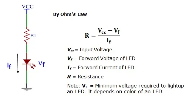
▲ Current limiting with resistor in LED circuits
Soldering Methods for Chip Resistors
Chip resistors are designed for surface mounting (SMD), and their installation generally uses one of the following methods:
- Manual Soldering: Suitable for prototyping and repair. Use a fine-tipped soldering iron (≤350°C) with tweezers.
- Reflow Soldering: Standard method in PCB manufacturing. Components are placed with solder paste and heated in a reflow oven.
▲ Video: How to solder SMD resistors manually
Precautions When Using Chip Resistors
- ESD Protection: Electrostatic discharge can damage high-precision or low-tolerance resistors. Always wear grounding straps during handling.
- Mechanical Stress: Avoid excessive force during soldering or rework. Bending PCBs can crack the resistor body.
- Power Derating: Always follow derating curves in datasheets to ensure resistors do not overheat under load.
- Package Constraints: Smaller packages like 0201 are harder to solder and have lower power ratings. Choose appropriate size based on application.

▲ Mechanical damage in chip resistor due to improper handling
🔧 How to Test or Replace a Chip Resistor
Using a Multimeter to Measure a Chip Resistor
The most straightforward way to test a chip resistor is with a digital multimeter set to resistance mode (Ω). Here's how to do it:
- Power off the circuit and discharge all capacitors to prevent inaccurate readings or damage.
- Set the multimeter to the appropriate resistance range.
- Place the probes on each side of the chip resistor. A good resistor should display its expected value within tolerance.
- If reading is significantly off or shows "OL" (open line), the resistor may be faulty.

▲ How to measure a chip resistor using a multimeter
Fault Diagnosis: Burnt or Drifted Resistors
Chip resistors may fail due to electrical overstress, overheating, or age. Common symptoms include:
- Burn marks: Indicate overheating, often due to overcurrent or incorrect power rating.
- Drifting resistance: If a resistor’s value has changed significantly, it's often due to thermal stress or moisture ingress.
- No continuity: The resistor has failed open and must be replaced.

▲ Burned and damaged chip resistor example
DIY Tip: Replacing SMD Resistor with a Through-Hole Resistor
In prototyping or emergency repair scenarios, you can replace a surface-mount resistor with a standard through-hole resistor:
- Carefully remove the damaged SMD resistor using tweezers and a soldering iron or hot air gun.
- Prepare a standard axial resistor of the same resistance and power rating.
- Trim its leads, form a U-shape, and solder it onto the original SMD pads.
- Ensure the replacement resistor is firmly soldered and doesn’t short to adjacent components.

▲ DIY repair: axial resistor replacing a chip resistor
▲ Video: How to test and replace surface-mount resistors
🛍️ Where to Buy Chip Resistors (B2B & Distributors)
Top Chip Resistor Brands
When sourcing chip resistors for industrial, automotive, or consumer electronics, choosing reliable brands ensures consistent performance and long-term reliability. Below are some of the most trusted names in the resistor manufacturing industry:
- Vishay – Known for precision and high-reliability resistors in medical, automotive, and industrial sectors.
- Yageo – One of the largest global suppliers with a wide range of cost-effective thick and thin film resistors.
- Panasonic – Offers premium resistive components with strong presence in automotive electronics.
- Samsung Electro-Mechanics – Supplies compact, high-performance chip resistors for mobile and consumer devices.
▲ Trusted chip resistor brands
Major Electronic Component Distributors
Whether you're a manufacturer or a design engineer, sourcing chip resistors through global B2B platforms ensures availability, documentation, and logistics support. Here are the most widely used distributor platforms:
- Onzuu – A fast-growing B2B electronic components distributor focused on quality sourcing, MOQ flexibility, and global supply support.

▲ Leading chip resistor distributors
Purchasing Tips: MOQ, Bulk Pricing, Lead Times
When purchasing chip resistors for mass production or R&D purposes, consider these important factors:
- Minimum Order Quantity (MOQ): Some platforms allow low MOQs (10 pcs), while others require reels (5000 pcs) for best pricing.
- Bulk Pricing: Unit price drops significantly with large volume orders. For example, a 0805 1kΩ resistor may cost $0.10 in small lots but under $0.005 in full reels.
- Lead Time: Check lead times during component shortages. Always validate if the part is “In Stock”, “Backorder”, or “Factory Lead Time”.
- Part Authenticity: Always buy from authorized distributors or trusted platforms like Onzuu to avoid counterfeit components.
▲ Video: How to buy resistors in bulk online
🔄 Chip Resistor Alternatives and Compatibility
Choosing the Right Replacement Model
When a specific chip resistor model is out of stock or discontinued, selecting a compatible alternative requires careful evaluation. Key parameters to match include:
- Resistance value (Ohm): Ensure exact or close resistance as per design requirements.
- Tolerance: For precision circuits, keep ±0.1% or ±1% tolerance; avoid ±5% unless allowed.
- Power rating: Must meet or exceed the original resistor’s wattage (e.g., 1/8W, 1/4W).
- Temperature coefficient (TCR): Critical for high-stability applications like analog or RF circuits.
- Package size: Physical dimensions must match PCB layout unless modification is allowed.
Compatibility Between Different SMD Sizes
Designers sometimes need to replace resistors of different SMD package sizes. This is possible, but requires attention to pad layout and thermal handling. Here's a basic compatibility reference:
| SMD Size | Alternative Size | Comment |
|---|---|---|
| 0402 | 0201 | May require pad modification; lower power handling |
| 0603 | 0402 or 0805 | Up/down possible with layout adjustments |
| 0805 | 0603 or 1206 | Electrical specs must be verified |
| 1206 | 0805 | Watch for power dissipation issues |
▲ SMD package substitution reference table
SMD vs Through-Hole Substitution: DIY Tips
In prototyping, repair, or hobbyist scenarios, it's common to replace SMD resistors with through-hole ones, or vice versa. Here's how to do it smartly:
- Through-hole ➜ SMD: Use adapter PCBs or solder thin wires to bridge leads to SMD pads.
- SMD ➜ Through-hole: Place the through-hole resistor flat on PCB and bend leads to align with pads. Use insulation to avoid shorts.
- Tip: Always double-check resistance value and tolerance, especially for low-ohm or high-precision applications.
▲ Video: Replacing SMD resistors with through-hole types (and vice versa)
Conclusion: Finding a compatible chip resistor replacement is often feasible with careful comparison of electrical and mechanical parameters. For mass production, always validate replacements with circuit simulation and testing.
📚 FAQs about Chip Resistors
1. Is a Chip Resistor the Same as an SMD Resistor?
Yes. A chip resistor is a type of Surface-Mount Device (SMD) resistor. These are compact, rectangular passive components designed for surface mounting directly onto PCB pads. So, the term "chip resistor" is often used interchangeably with "SMD resistor."

▲ Chip resistors are a sub-type of SMD resistors
2. How to Tell If a Chip Resistor Is of Good Quality?
Assessing chip resistor quality involves:
- Brand reliability: Trusted manufacturers like Vishay, Yageo, and Panasonic offer consistent quality.
- Markings: Clear and correct resistance code without smearing or missing digits.
- Packaging: Proper ESD protection, reel labeling, and moisture-proof bags.
- Electrical test: Use a multimeter to verify resistance value matches the code.
Cheap or counterfeit chip resistors may suffer from tolerance drift, higher temperature coefficient, or unreliable solderability.
3. What’s the Difference Between a Chip Resistor and an SMD Resistor?
Technically, no difference. A chip resistor is a specific form of SMD resistor, optimized for rectangular shape and automated pick-and-place assembly. The term “SMD resistor” can refer to any resistor made for surface-mounting, while “chip resistor” usually implies flat, rectangular types.
4. How to Know If a Chip Resistor Is Damaged?
Use a multimeter in resistance mode:
- If the reading is open (OL), the resistor might be burned out or cracked.
- If the resistance is way off from the nominal value (e.g., a 10kΩ reading 2kΩ), it may have drifted or partially shorted.
- Visual signs: Darkening, cracking, or lifted pads often indicate overheating or mechanical stress.
▲ Video: How to test if a chip resistor is faulty
5. Can I Solder a 0402 Resistor by Hand?
Yes, but it's not beginner-friendly. 0402 resistors are only 1.0mm × 0.5mm in size. To hand-solder:
- Use fine-tipped soldering iron (≤0.5mm)
- Apply flux and tweezers to hold component
- Use low temperature solder paste for better control
- Practice with 0603 or 0805 first if you're new to SMD soldering
▲ Video: How to manually solder 0402 resistors
Tip: Always use ESD-safe tools and avoid excessive heat when handling small chip resistors.
🧩 Conclusion: Why Chip Resistors Matter in Electronics
Chip resistors are far more than tiny black rectangles — they are fundamental components in every modern electronic circuit. From your smartphone's power management to a car's ECU, chip resistors enable voltage regulation, signal conditioning, and current limiting with high precision and reliability.
✅ Key Considerations When Choosing a Chip Resistor:
- Power Rating vs. Size: Ensure the package size (e.g., 0603, 0805) matches your design’s thermal and power needs.
- Resistance Value & Tolerance: Choose appropriate ohmic value with precision based on circuit function (e.g., ±1% for general use, ±0.1% for precision circuits).
- Material & Stability: Use thin-film resistors for low-noise and stable applications; thick-film for general-purpose cost-effective solutions.
- Environment: Consider temperature coefficient and moisture resistance, especially in automotive or outdoor electronics.

▲ Different chip resistor sizes and applications
🌐 Why They Matter:
In high-volume production, choosing the right chip resistor helps engineers optimize PCB space, improve thermal performance, reduce BOM cost, and ensure long-term stability. In other words, resistors are tiny but critical to reliability, manufacturability, and affordability of your entire design.
🛒 Recommended Products:
| Part Number | Resistance | Package | Precision | Vendor | Link |
|---|---|---|---|---|---|
| RC0402FR-0710KL | 10kΩ | 0402 | ±1% | Yageo | View |
| CRCW080510K0FKEA | 10kΩ | 0805 | ±1% | Vishay | View |
| ERJ-6ENF1002V | 10kΩ | 0805 | ±1% | Panasonic | View |
For bulk orders and distributor support, visit Onzuu — your trusted electronic component B2B platform.